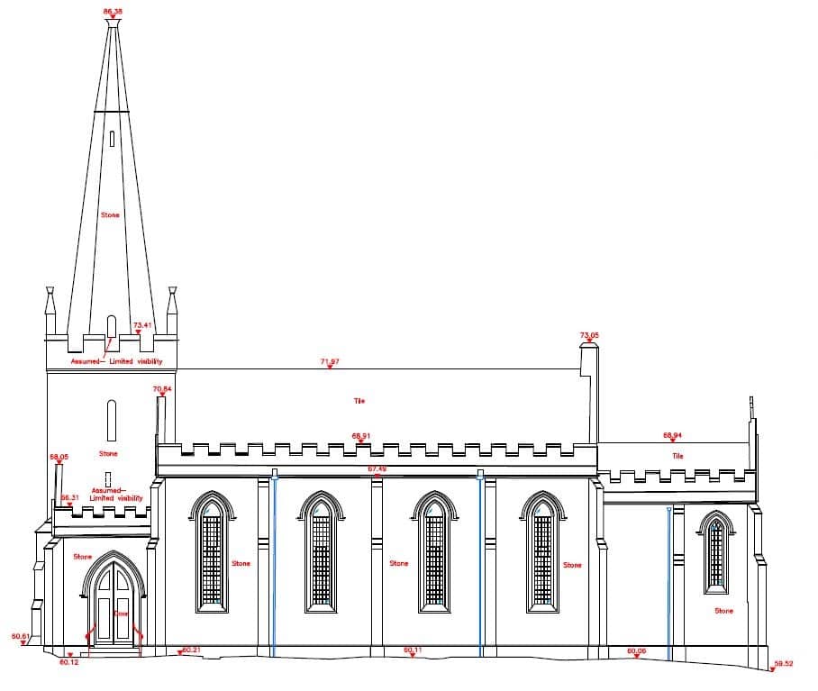
How architects can survey and draw a complicated elevation like this by taking just one measurement.
In 4 easy steps
What you’ll need is:
1. Some free-to-download software called Meshroom & CloudCompare
2. An ordinary camera
3. A tape measure
4. A CAD program
About Meshroom and CloudCompare
Meshroom is a free and open-source photogrammetry software from AliceVision. Photogrammetry software enables you to automatically create a 3D scene using a series of photographs. Photographs are dragged and dropped into the software and, under the default settings, a 3D model in Wavefront OBJ format is created. Meshroom requires an Nvidia GPU and operates on Windows and Linux.
CloudCompare is a free 3D point cloud processing software that can also handle triangular meshes and calibrated images. CloudCompare provides a set of basic tools for manually editing and rendering 3D point clouds and triangular meshes. Ortho images can be created to take views of 3D models into CAD and other software. CloudCompare is available on Windows, Linux and Mac OS X platforms, for both 32 and 64 bits architectures.
Accuracy
So what sort of accuracy can be achieved using this technique? Is it as accurate as using a laser scanner or professional-grade photogrammetry software that costs £1000's? No, it's not. But is it more accurate than guessing the position of features you can't measure to, lining up things by eye, trying to count brick courses, or estimating heights in relation to other buildings? Yes, it's considerably more accurate than that. If carried out carefully, it's a quick and easy way to get great results that are perfectly suitable for tasks that don't require great degrees of precision. If you want to draw up something for a feasibility study, make a markup for repairs work, or if you need to get some information about contextual elevations for a planning application then it will be accurate enough for those purposes. Experiment before trying it on a live project and always remember to measure the longest distance you can - and take a few checks to confirm your results. Over short distances, there is no reason you can't achieve centimetre accuracy, and for larger objects, most results should be within the range of 100mm or so, but this will all depend on how you apply the measurement you take and your photography. If in doubt best get a surveyor in to help.
Step 1 - Take photographs of the facade and just one measurement
Before you start make sure image stabilization is turned off in your camera and remember not to change the zoom settings while shooting your photographs.
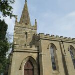
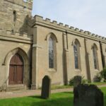
Start at one end of the building standing far enough back so you can see as much of the facade as possible.
Take a series of photographs of the entire facade making sure that each one overlaps the next by at least 50%.
|
|
Move along a few paces and repeat the process. Keep moving along taking a new series of photographs from each position until you reach the other end of the building.
Measure the distance between 2 features on the facade. The longer the distance, the more accurate your survey will be.
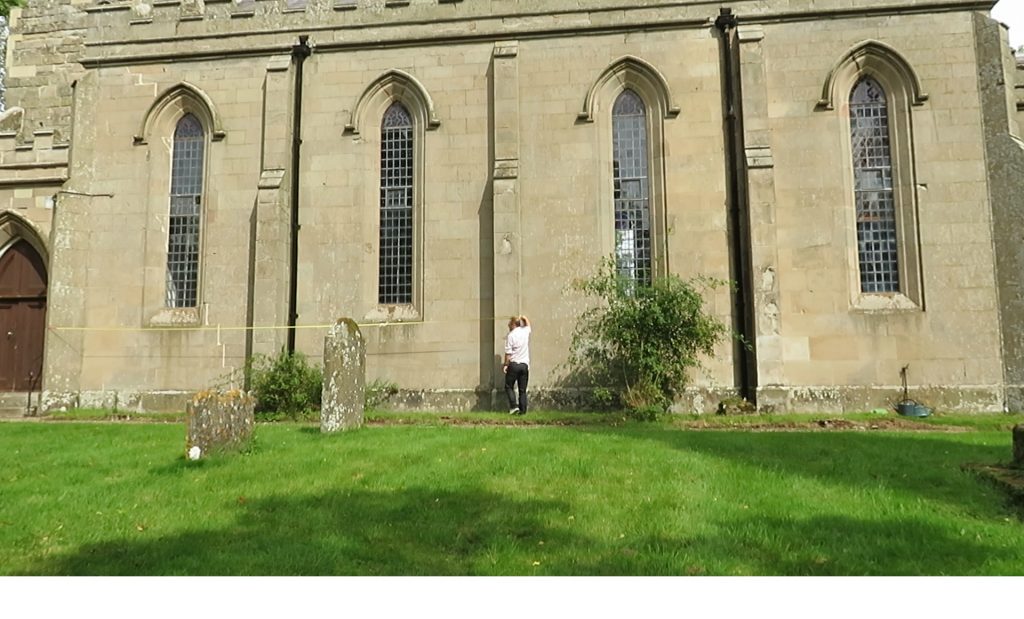
For this project around 40 photographs in total were taken from 5 different positions.
Before progressing please download and install Meshroom and CloudCompare.
Step 2 - Use Meshroom to process your photographs into a 3D model
Drag & drop your photographs into Meshroom.
Save your project then process your photographs into a 3D model by clicking on the Start button.
A project of this size will take around one and a half hours to process. The software's default settings will produce a good model and should not need altering.
Step 3 Use CloudCompare to turn your 3D model into an ortho image
Browse to your Meshroom project folder, open the Meshroom Cache folder and then the Texturing folder. There will be a folder in Texturing that will contain your 3D model in OBJ format along with some other associated files.
Drag & drop the file called texturedMesh.obj into CloudCompare.
Hold down the left mouse button and rotate the model so the view approximately shows the elevation correctly.
To reset the rotation point click on the + icon then double click on the point on the model that you want to rotate around.
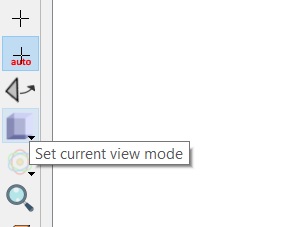
Click on the Set current view mode button
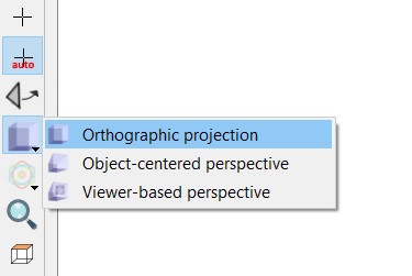
Select Orthographic projection.
The right mouse button can be used to pan and you can zoom in and out using the scroll wheel.
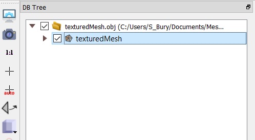
Select the texturedMesh in the explorer tree.
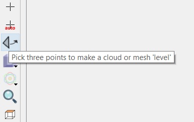
Select the Pick 3 points to make a cloud or mesh ‘level’ icon.
Identify a long horizontal line such as a brick course on your model. This should preferably be not too far above the ground.
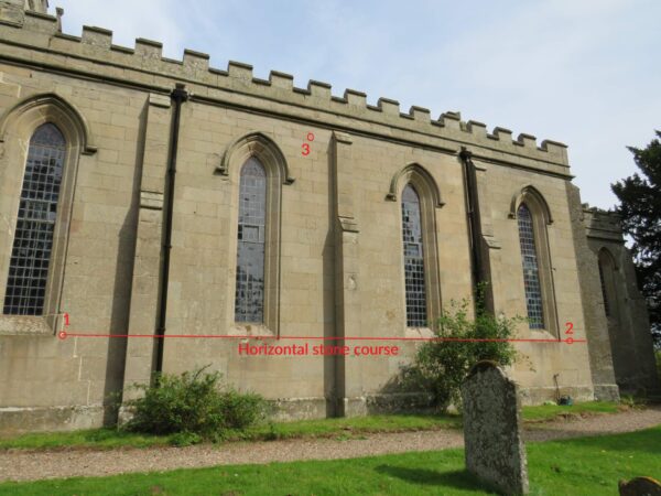
Select a point near the left hand end of that line (1) then another towards the right hand end (2).
Then select a point on the same face as high as possible above the other 2 points (3).
Make sure all 3 points are on the same wall face.
This process will set your model so the view is a true elevation, with the model being flat in the current view and truly vertical.
Pan and zoom so your model fills the entire view.
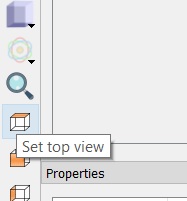
Click on the Top View icon to make sure your view is still orthogonal.
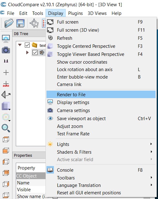
Select Display then Render to file from the top menu.
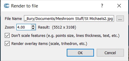
Choose a file name and a location to save it. Set Zoom to 4, make sure both boxes are checked and press OK to create your ortho image.
Step 4 - Creating an accurate CAD elevation drawing from your ortho image
Open a new drawing in your CAD program and create a separate layer for your ortho image.
Make the image layer active and import or attach your ortho image.
Scale your ortho image so it’s the correct size using the measurement you took on site.
It's a good idea to get the image roughly to scale, then draw a horizontal line across it that is the same length as the distance you measured across the facade on site. Move the line so one end of it overlays the point on the facade you measured from, then use scale using a reference to change the size of the image so the 2 points measured between are scaled to match the line.
Lock the image layer and set the layer you want to draw in as active. Locking the layer prevents the ortho image being accidentally moved during the drawing process.
Use your normal CAD functions to draw over the ortho image to create your accurate elevation drawing.