A Quick Guide To CAD Measured Building Survey Drawings

The example drawings we’ll be looking at are from our survey of this Victorian church in Birmingham.
Introduction
Measured Building Surveys are often delivered as a set of 2D CAD drawings that show different elements and views of a building. When commissioning a Measured Building Survey it’s important to know which drawings you need. In this quick guide we’ll explain 2D CAD Measured Building Survey drawings and what information they show. The drawings we’ll be looking at are from a Measured Building Survey of a church. This project was laser scanned and 3D modelled in Revit software then the 2D CAD drawings were exported directly from that model. When working with a complicated building such as this church, a 3D Revit model is a great additional help to the design team and allows any extra drawings that are needed to be quickly created.

The Revit model that our CAD drawings were exported from for this guide.
What are the 7 different drawing types for a 2D CAD Measured Building Survey?
- Floor Plans - a top down view of each floor
- Elevations - a straight-on view of the outside faces of the building
- Sections - a sliced view through the building
- Reflected Ceiling Plans - a plan of the detail on a ceiling
- Roof Plans - a top down view of the building;s roof
- Sectional Elevations - a sliced view through the building that also shows walls and features in the background
- Internal Elevations - drawings showing the details on internal walls
Click on the links above to find out directly about each drawing type or scroll down to read the whole article.
The basics for every CAD survey drawing
Before we start it helps to understand the basics about CAD drawings and the information on the drawing sheet that helps us read and understand the drawing.
CAD Layers
CAD drawings contain a layering system that allows each elements to be easily identified, and if necessary, turned off to remove them from view or managed in other ways. Elements such as walls, doors, windows, text and sanitary fittings are usually all assigned to their own named layers. All the elements in the drawings featured in this guide have been put onto our easy-to-understand layering system.
Title Blocks
The title block is an essential part of any CAD drawing. It usually contains information such as notes, details about the project, the drawing number and a key to abbreviations and symbols. Let's take a look at a few of these elements.
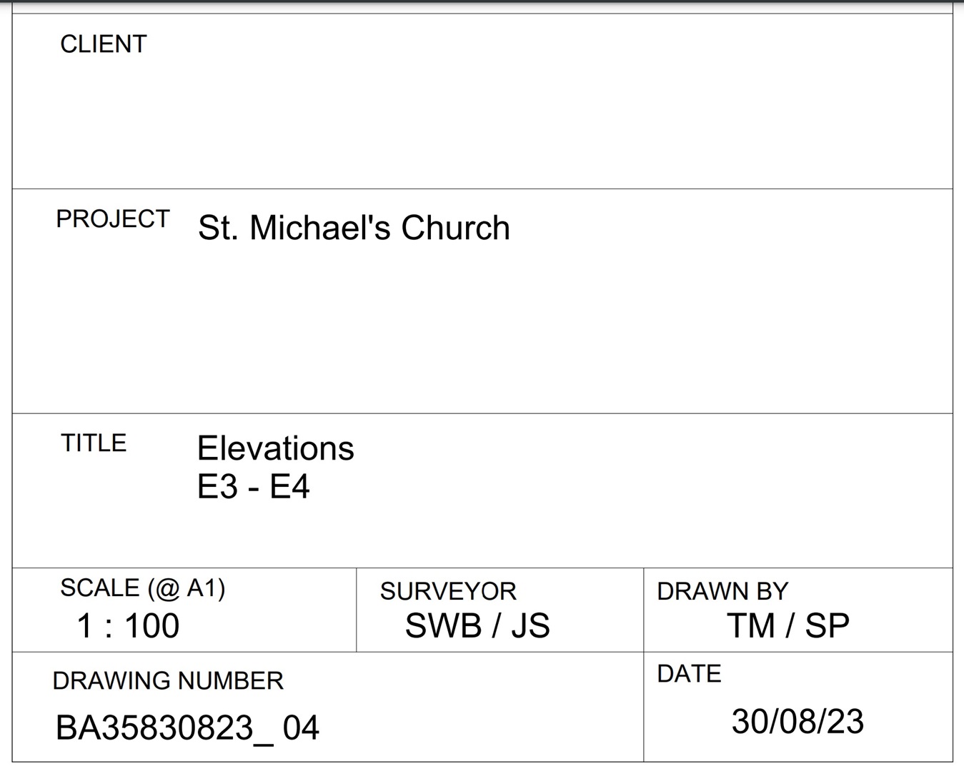
Project detail boxes in the title block
Project Details
Details such as who the client is, the drawing title, its scale, who was it surveyed and drawn by, the drawing number and its date of issue should be shown in the title block. The drawing number should always be referred to if you have any questions about a survey. The BA prefix in our drawing numbers identifies it as being produced by Bury Associates, the next 4 digits is our project number (in this case 3583), the next 4 are the month and year the survey was commissioned (August 2023) and the 04 at the end indicated that it is drawing sheet number 04.
Notes
The notes on a drawing often contain important information about the drawing such as the origin of the grid and datum, specifications and any clarifications. These notes should always be kept on a drawing - even if the surveyor's original title block is replaced.
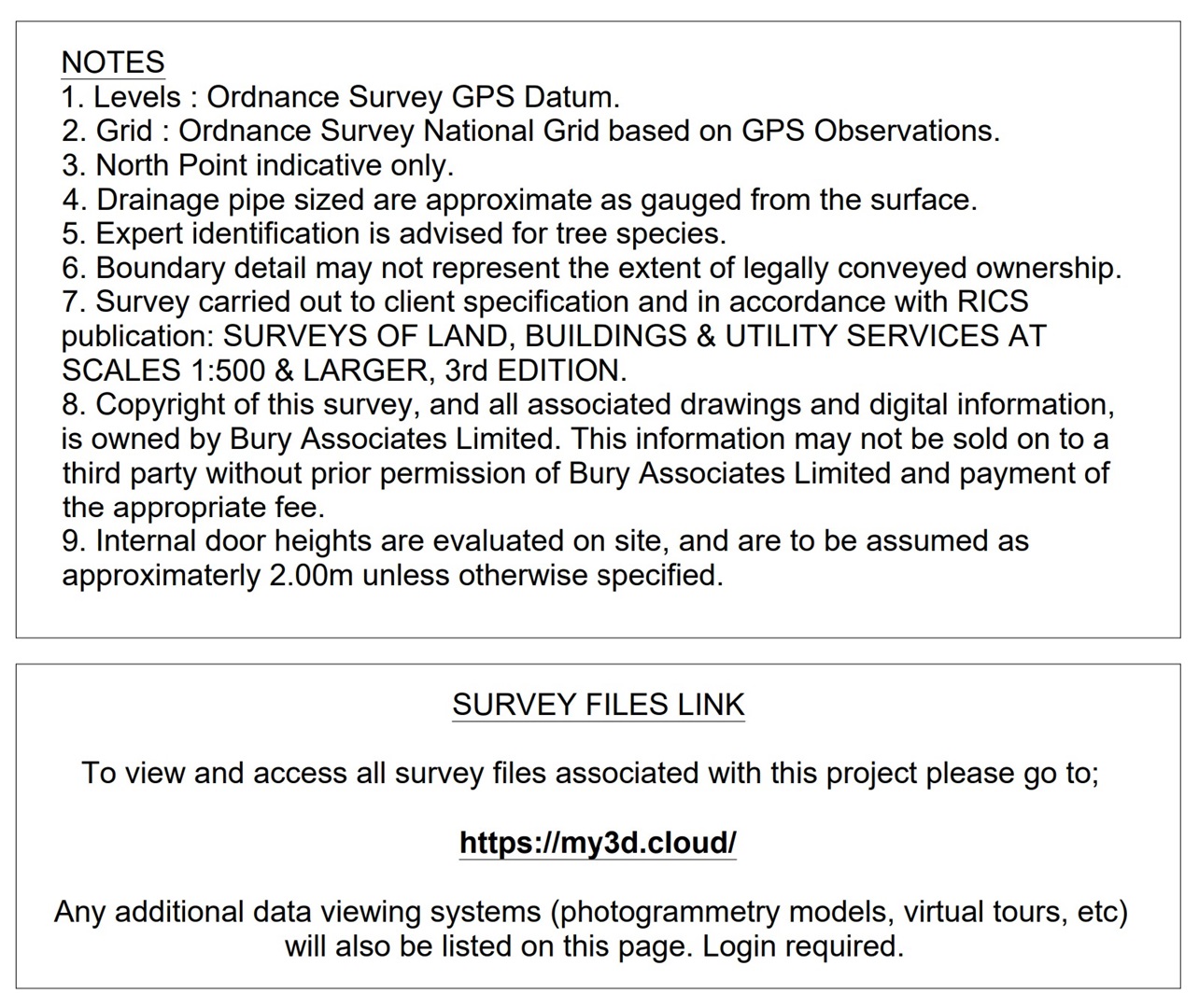
The drawing notes in the title block with a download link for the survey's digital deliverables.
Scale Bar
A scale bar is an essential feature for any plan or map. Digital survey drawings are often set up on drawing sheets that, to be true-to-scale, need to be printed out in a large format such as A1. When they are viewed on a computer screen or printed out at A3 or A4 for convenience, a scale bar is essential for checking and understanding the true scale.

Control Points
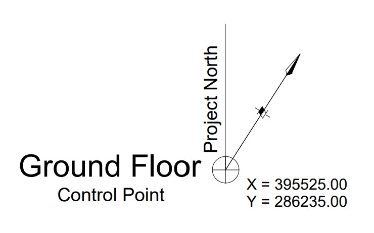
Control Points show the relationship between the component parts of the survey, such as the plans of different floors of the building. Often multiple plans are plotted next to each other on the same drawing sheet. A Control Point is added to each plan so if it needs overlaying onto another floor it can be copied from its own Control Point to that of the other plan. If a Topographical Survey has been also been carried out, a Control Point is placed on that too to show the building survey's relationship to it.
This building survey has been rotated so that the main walls run perpendicular to the drawing sheet so it's easier to use. The Control Point also indicates the floor plan's relationship to true north and to the Ordnance Survey grid.
1. Floor Plans
Overview
A Measured Building Survey floor plan is a detailed, scale drawing that represents the layout and dimensions of a building as seen from above. It accurately depicts the size, position, and relationship of rooms, walls, doors, windows, and other structural elements within the building. This type of floor plan is essential for architects, engineers, and property developers, providing a precise and comprehensive view of the building's physical space, which is crucial for planning, design, renovation, or documentation purposes.

Measured Building Survey Floor Plan Drawing Sheet. The positions of Sections and Elevations are marked onto the plan information.
What Information Is Typically Shown On A Measured Building Survey Floor Plan?
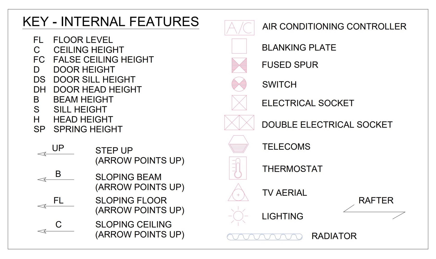
To help keep a floor plan uncluttered and easy to understand, abbreviations and symbols are used on the drawing to show much of the information. Every floor plan drawing should have a key to explain the meaning of these abbreviations and symbols.
Although floor plans can be used for many purposes and some can even be just schematic, a Measured Building Survey Floor Plan for architectural purposes should always show the following information as a minimum:
- Walls, including their true thicknesses
- Doors with swing directions
- Windows with the correct frame position and width
- Steps and stairs
- Ceiling details, such as changes in slope, beams, hatches & skylights*
- Sanitary fittings
- Floor levels
- Ceiling, door and window heights
*Simple ceiling configurations often can be shown as linework on the floor plan but when more complicated or ornate ceiling are often drawn on a separate Reflected Ceiling Plan.
Additional Features That Are Often Included
- Slope arrows showing the direction of floor and ceiling slopes
- Electrical sockets, switches, fuse boxes, telecom systems, alarms, heating systems
- Lighting
- Gas, Water and electric meters and service entry positions
- Radiators
- Ducts, cables, pipes
- Cupboards and built-in fixed furniture.
- Skirting and coving
- Drains and manhole covers
- Construction materials and surface finishes
- Floor board and joist directions
- Statues and architectural embellishments
2. Elevations
Overview
A Measured Building Survey Elevation is a type drawing that depicts the external faces of a building in a flat representation. This view shows the vertical elements and features of the structure, such as windows, doors, and decorative details, with precise dimensions and scale. Elevations are crucial for understanding the aesthetic and functional aspects of a building's design, aiding in the restoration, renovation, or construction processes by providing a detailed and accurate view of the building's façades.
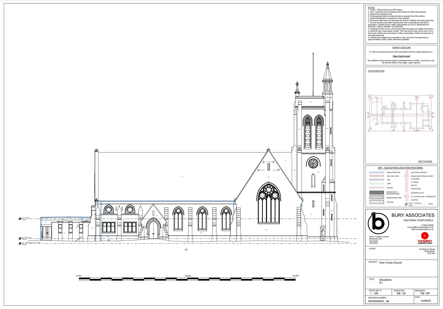
A CAD Elevation drawing of the church
What Does A CAD Elevation Drawing Show?
Measured Building Survey Elevation Detail
Elevations can show a range of detail from just simple outlines through to every single stone being drawn - depending on the purpose of the survey. Generally, Measured Building Survey Elevation drawing will include:
- Wall lines
- Outlines of architectural detail
- Windows - frames, sills, glazing bars etc.
- Doors - frames, relief, handles, locks, large hinges, letterboxes
- Rainwater goods - downpipes, gutters etc.
- Soil vent pipes and other pipework
- Vents, airbricks
- Chimneys, pots and flues
- Damp proof courses
- Quoins, lintels, structural timber and edging stonework
- Materials
- Roof lines
- Architectural ironwork
- Internal floor levels
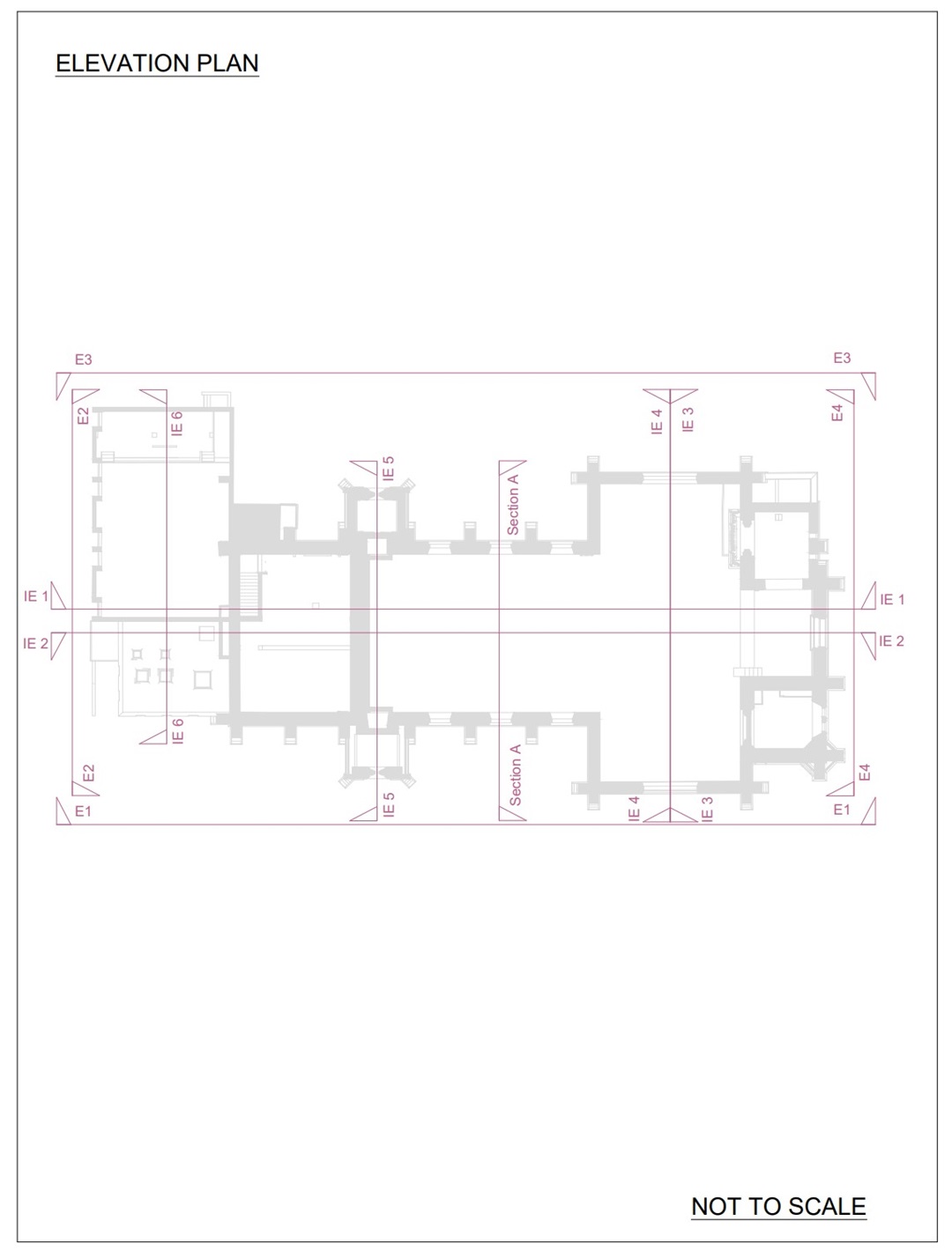
The title blocks of the drawing sheets for External Elevations, Internal Elevations, Sections and Sectional Elevations will contain a Key Plan that shows the position and facing direction of each of those items.
3. Sections
Overview
A measured building survey section is an illustrative cut-through drawing of a building, providing a detailed view of its internal structure, from the roof down to the foundation. This cross-sectional representation reveals the relationships between different levels and spaces within the building, including floor heights, room dimensions, and structural elements like beams and columns. Sections are essential for understanding the internal layout and design of a building, offering insights into its construction and spatial dynamics, which are invaluable for renovation, planning, and architectural analysis. Sections are sometimes defined as cross sections or long sections. Usually cross sections are taken perpendicularly through narrower parts of a building, whereas long sections cut through the whole length of a building.
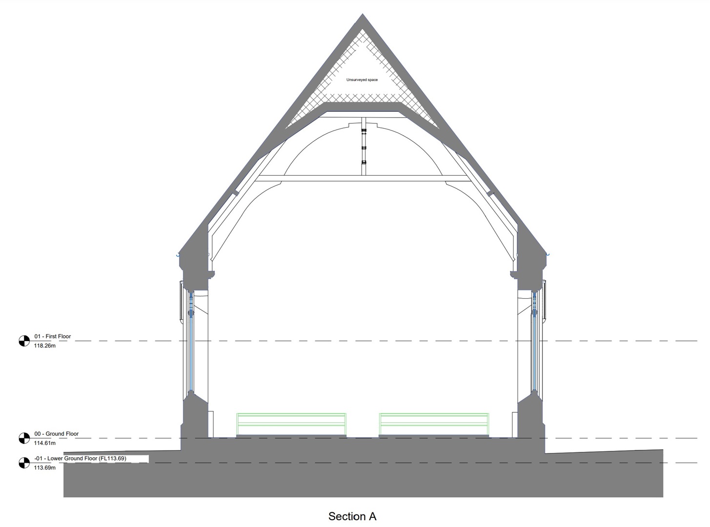
A Section through the church
Section Detail
The detail shown in a building section drawing will depend on what that section cuts through. Sections are often drawn through important features such as roof trusses and staircases to give a better understanding of their relationship with the rest of the building.
4. Reflected Ceiling Plans
Overview
Reflected ceiling plans, often known by the abbreviation RCP, are architectural drawings that depict the ceiling of a building as if it were reflected onto a mirror placed on the floor. These plans show the layout of ceiling elements such as lighting fixtures, HVAC components, ceiling grids, and decorative features, in relation to the floor plan. They are essential for interior design, lighting design, and for understanding the integration of ceiling systems with other building services, providing a comprehensive view of the aesthetic and functional aspects of a building's upper interior space.
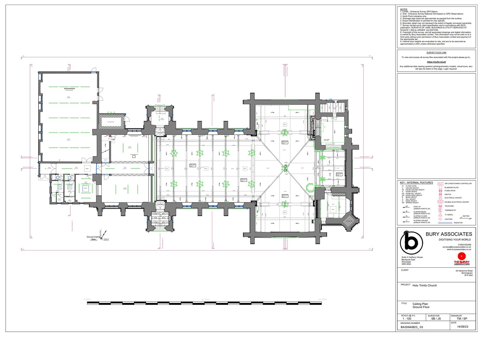
The church's Reflected Ceiling Plan
Features Typically Drawn on an RCP
- Beams
- Ceiling drops and changes in slope
- Cornices, ceiling roses and other ornate plasterwork
- Vents, hatches, skylights
- Ducts, pipes, cables
- Air conditioning ducts and units
- Lighting
- Materials
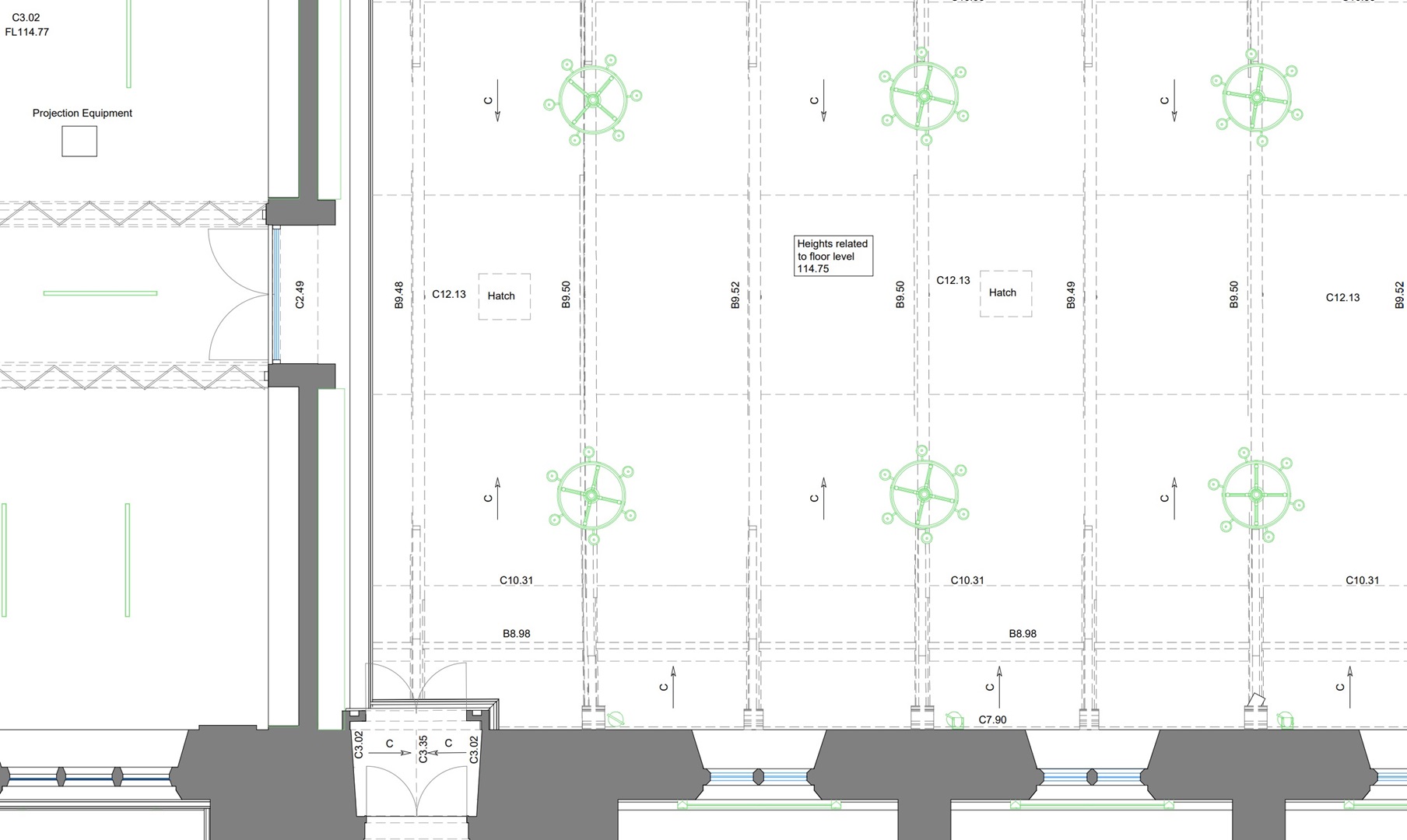
Part of the church's RCP showing lighting, beams and other features
5. Roof Plans
Overview
A roof plan is an architectural drawing that presents a bird's-eye view of a building's roof. It details the roof's design, including its shape, slopes, drainage, and any features such as chimneys, vents, and skylights. This plan is crucial for understanding the roof's structure and layout, essential for tasks like roofing installations, repairs, and ensuring proper water drainage. It serves as a vital guide for architects, builders, and roofers in both the design and construction phases of a building project.
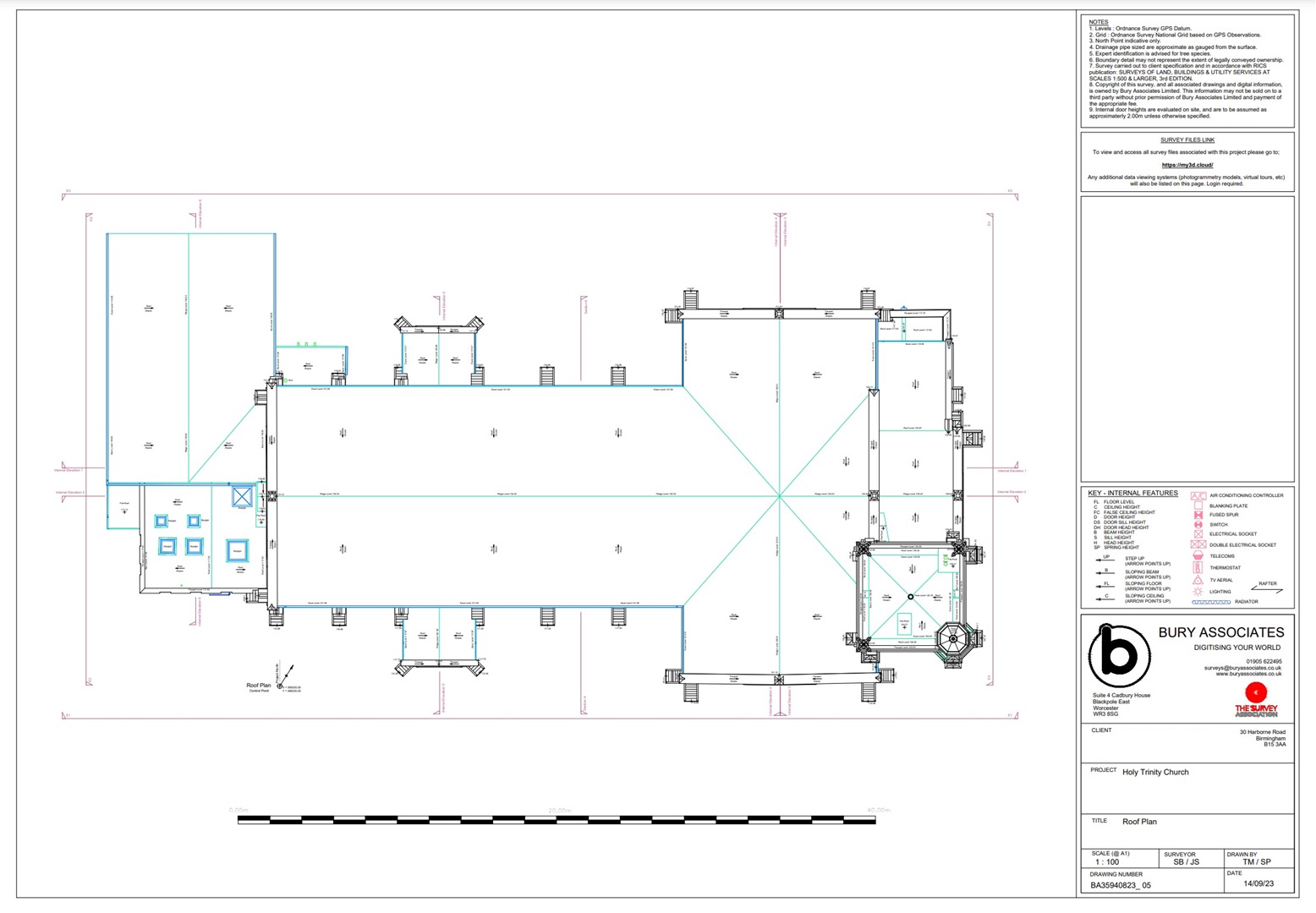
The church Roof Plan
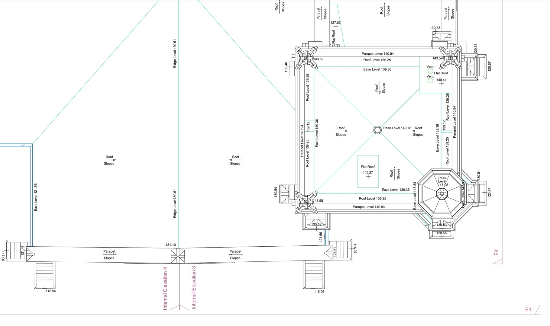
Roof Plan detail around the church tower
What You Can Expect To See On A Measured Building Survey Roof Plan
- Breaklines and edges
- Slope directions
- Ridge, eave, parapets and flat roof levels
- Chimneys, pots and flues
- Architectural stonework
- Architectural ironwork
- Guttering, pipes and drainage details
- Flashing
- Materials
6. Sectional Elevations
Overview
Sectional elevations are architectural drawings that combine elements of both sections and elevations, providing a detailed view of a sliced portion of a building's interior or exterior. These drawings illustrate how different levels of a structure relate vertically and how the internal features align with the building's façade. They are particularly useful for understanding the intricate details of a building's construction, including staircases, joinery details, and the interaction between various architectural elements, making them invaluable in detailed design and construction planning.
CAD drawing showing 2 Sectional Elevations through the church.
Sectional Elevation Drawing Detail
Sectional elevations show the main architectural features that would appear on external elevations and sections but often show greater detail for the internal wall faces. These additional features can include:
- Radiators
- Fire places
- Lighting
- Sockets, switches, fuse & alarm boxes
- Fixed furniture
- Skirting and coving
- Architectural embellishments
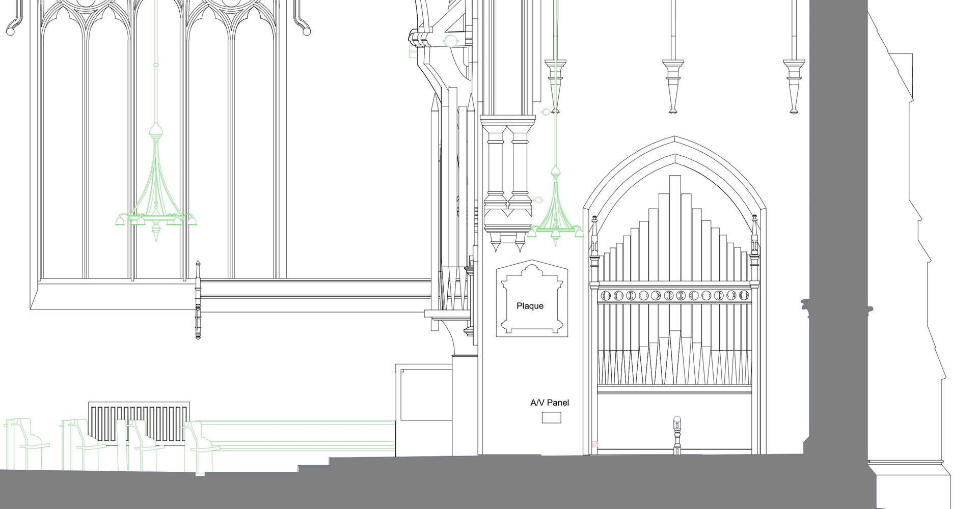
Close-up of a Sectional Elevation showing extra internal detail.
7. Internal Elevations
Overview
Internal elevations are architectural drawings that detail the interior surfaces of a room or space within a building, viewed from one side. They show the layout and design of features like doors, windows, built-in furniture, and other architectural elements, often including details about finishes and fittings. These elevations are crucial for interior design and renovation projects, as they provide a clear and detailed visual reference of the interior aesthetics and functional aspects, aiding in the precise planning and execution of interior spaces. Internal elevations can appear to be the same as sectional elevations but they are significantly different. Sectional elevations provide a view into the building taken from where the section cuts through the walls - this view can include items in the foreground as well as the detail of the wall in the background. Internal elevations tend to just show the detail that is physically on the faces of the internal walls.
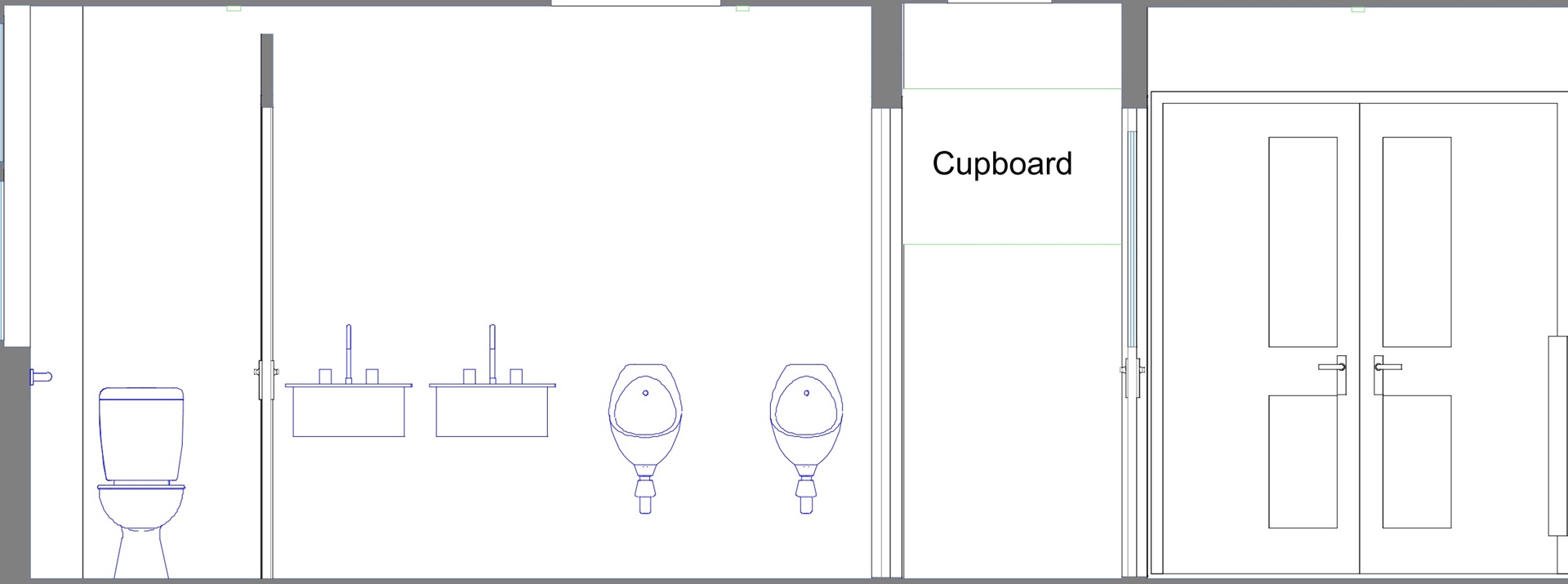
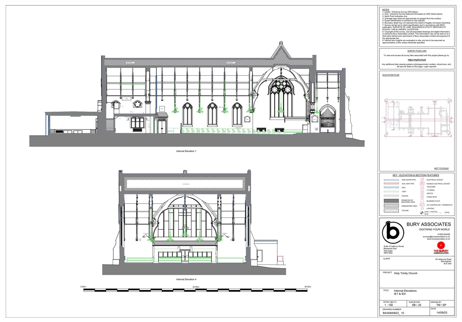
An Internal Elevation showing the position of sanitary fittings on the wall.
Internal Elevation Detail
- Radiators
- Fire places
- Lighting
- Sockets, switches, fuse & alarm boxes
- Fixed furniture
- Skirting and coving
- Architectural embellishments
Summary
2D CAD drawings are a very flexible way of delivering Measured Building Surveys. This guide explains what is included as standard but surveys can be tailored to suit your own requirements and the needs of any project. They can be produced on their own or exported from a 3D Building Information Model (BIM) created in a software such as Autodesk's Revit.
For more information about 2D CAD or 3D Revit Measured Building Surveys call us today on 01905 622495 or use one of the links on this website to send us a message.
Steve Bury is the Managing Director of Bury Associates, a land and measured building survey company based in the UK. With over 40 years of experience in surveying, Steve Bury established Bury Associates in 1997 to combine the provision of high quality digital surveys with exceptional customer service. Steve has also designed software applications for measuring buildings to automatically create survey drawings.